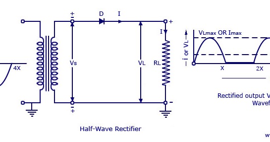
Half Wave Rectifier Circuit Diagram
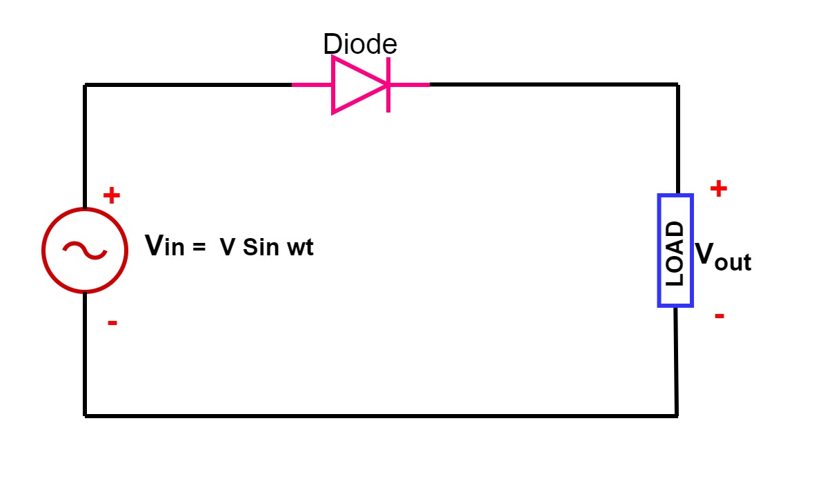
Half wave rectifier ☑ half wave rectifier circuit using one diode Half wave rectifier: principle & working
HALF WAVE RECTIFIER BY SRAVANI ANNAPURNA.A(221710303057)
Single phase half wave rectifier- circuit diagram,theory & applications Wave rectifier half circuit diagram hwr Rectifier circuit half wave diagram fast build forget don if click
Wave half rectifier diode ac voltage supply output peak circuit inverse operation piv dc load value average input rectification signal
Rectifier wave half working circuit principle characteristics positive rectifiers using diode cycle load voltage types input elprocusSingle phase half wave rectifier- circuit diagram,theory & applications Rectifier half diode circuitdigest breadboard diodesRectifier circuit diagram.
Rectifier circuit diagramRectifier circuit applications Rectifier wave half circuit diagram rectification diode ac operation crystal connected used supply shown below throughBuild a fast half-wave rectifier circuit diagram.
Bridge rectifier circuit
Rectifier wave half circuit bridge diagram circuits schematic diodes simple graph transistors learn northwesternRectifier wave circuit output waveform input etechnog wiring Half wave and full wave precision rectifier circuit using op-ampHalf wave rectifier.
Half wave rectifier by sravani annapurna.a(221710303057)Wave half rectifier diagram circuit working principle Half wave rectifier – definition, working, circuit diagram, theoryRectifier transformer tapped waveform.

Rectifier wave half positive engineering stack
What is half wave and full wave rectifier? .
.


