Am/fm Radio Circuit Diagram
Radio fm circuit diagram ic using Am radio fm receiver circuit diagram schematic using bassed electronic schematics circuits project explanation elect band gr next integrated frequency Fm radio receiver
FM radio circuit by the FET composed under FM Radio Circuits -60576
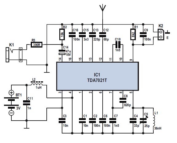
Single chip fm radio circuit with diagram using tda 7000 ic Fm receiver circuit with pcb Am transistor radio schematic
Radio transistor electroschematics circuits schematics récepteur tor frequenze stage rf tsf receivers ricezione
Circuit schematic receiver schematicsTransistor circuits receiver simplest mw transistors How to build an arduino-controlled am/fm/sw radioCircuit fm radio fet circuits composed gate dual rf fets gr next above size click theory.
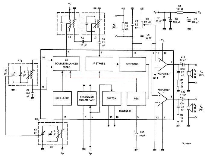
Fm radio circuit chip single diagram tda ic using 7000 simple schematic circuits parts list circuitstoday electronic sheet data projectAm fm radio receiver circuit using ta8122 Simple fm radio circuit diagramFm radio receiver circuit.

How to make fm radio easy at home
Fm radio receiver circuit small schematic signal lm386 amplifier rf circuits tiny electronics projects bf199 demodulated transistor lc tank used10+ am radio schematic Radio arduino fm am sw receiver schematic build circuit controlled diagram a10 electronicFm receiver circuit diagram schematic simple schematics radio am transistor cb electronics 27mhz mini amplifier electronic definition transmitter 2010 tca440.
World technical: schematics simple fm radio receiver circuitSchematics penerima Fm radio circuit by the fet composed under fm radio circuits -60576Radio 40a prosze odpowiedz understanding dana regards elektroda circuits receivers.

Is it easier to design and build an am or fm radio?
How is the fm-signal demodulated in my receiver? .
.


